
How to Choose the Right Pressure Relief Valve?

Choosing the right Pressure Relief Valve is a safety decision, not a simple purchasing task. The valve must match the system’s pressure, temperature, fluid, connection size, and discharge capacity. A mismatch may cause leakage, unstable operation, or dangerous overpressure. Small details matter.

Imagine a steam line warming before production begins. The gauge rises slowly, the pipe vibrates, and the relief valve must respond without hesitation. In this situation, engineers review the set pressure, allowable accumulation, backpressure, and required flow rate. They also check whether the medium is steam, water, gas, or a corrosive chemical. Each fluid can demand a different material and valve design.

Reliable selection begins with verified data. Consult equipment drawings, operating records, manufacturer specifications, and recognized engineering standards. A qualified professional should confirm the sizing calculation and installation arrangement. The discharge pipe needs proper support and a safe outlet. It should never be treated as an afterthought.

Real systems are rarely perfect. Pressure readings can drift. Maintenance records may be incomplete. Even experienced teams can overlook temperature changes during startup. That deserves attention. A careful review should include inspection access, testing intervals, corrosion risks, and future operating conditions. The cheapest valve may not deliver the lowest lifecycle cost. A robust choice protects people, equipment, and production continuity while remaining practical to maintain. This guide explains the critical questions behind that choice and highlights common mistakes that deserve a second look.
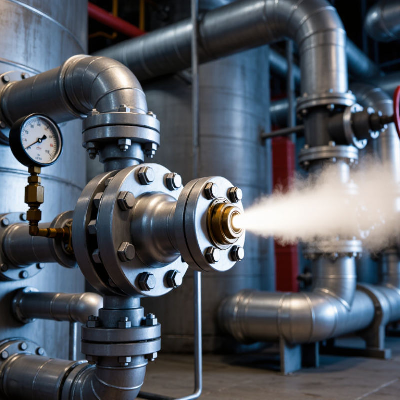
How to Choose the Right Pressure Relief Valve?

Establish MAWP and ASME VIII’s 10% accumulation criterion

How to Choose the Right Pressure Relief Valve?

Establish MAWP before selecting a pressure relief valve. MAWP means the highest pressure a vessel can safely withstand at its specified temperature. Engineers determine it from the weakest pressure-retaining component, not from the strongest section. A shell may look robust, while a flange or gasket governs the limit. ASME BPVC Section VIII, Division 1, requires the valve set pressure to remain at or below MAWP under normal conditions.

The 10% accumulation criterion is central to this decision. For a single relief device, vessel pressure generally cannot exceed 110% of MAWP during relieving conditions. ASME permits up to 116% with multiple devices and 121% for certain fire exposure cases. These figures appear in UG-125 and UG-134 of the 2023 ASME code. They are not convenient design margins. They define controlled overpressure limits. API 520 Part I and API 521, 2020 editions, also guide sizing, installation, and credible overpressure scenarios.

Check the details twice. A valve set at 10 bar does not automatically protect a vessel with a 10 bar MAWP. Backpressure, temperature correction, inlet losses, and discharge capacity can change actual performance. I have seen calculations treat fire exposure like routine operation. That is a serious mistake. The process hazard review should test blocked outlets, runaway reactions, thermal expansion, and utility failures. Small assumptions can produce large consequences.

Select spring- or pilot-operated valves by fluid, temperature, and backpressure

How to Choose the Right Pressure Relief Valve?

Selecting a pressure relief valve starts with the fluid, not the catalogue image. Identify whether the medium is gas, steam, liquid, or a two-phase mixture. Viscosity, corrosion, and suspended particles also matter. A spring-operated valve is often practical for clean fluids and straightforward systems. It has fewer moving parts and can be inspected easily. However, its spring may react to built-up or superimposed backpressure. That can change the opening behavior.

Temperature narrows the material choices quickly. Check the process temperature, cold-start condition, and possible heat tracing failure. Seal materials must tolerate the entire operating range, not only the normal temperature. Pilot-operated valves can offer tighter shutoff and stable performance at higher pressures. They may suit systems with variable backpressure. Yet small pilot passages can plug when the fluid carries dirt or crystallizes. Clean service is important.

Measure backpressure at the valve outlet. Separate constant superimposed pressure from pressure created during discharge. A conventional spring valve may need correction, a balanced design, or a different set pressure. Pilot-operated equipment can reduce some backpressure effects, but it is not automatically the best choice. I have seen neat selection tables hide poor field conditions. One overlooked cold spot caused trouble. Review the discharge piping, maintenance access, sensing-line layout, and actual fluid behavior with a qualified engineer. Test assumptions against operating data. Calculate the valve capacity using credible process conditions, then verify the result against applicable engineering standards.

How to Choose the Right Pressure Relief Valve?

Select spring- or pilot-operated valves by fluid, temperature, and backpressure.

Reference screening values for built-up backpressure expressed as a percentage of set pressure. Final limits depend on valve construction, sizing, fluid properties, temperature, and applicable design standards.

Fluid

Conventional spring valves are often preferred for dirty or polymerizing services because their sensing mechanism is comparatively simple. Pilot-operated valves require clean, compatible fluid and reliable pilot passages.

Temperature

Check the temperature rating of the body, spring, seals, bellows, pilot, and tubing. Low-temperature and high-temperature services may require special materials or insulation.

Backpressure

Conventional spring valves are commonly screened around 10% built-up backpressure, balanced-bellows designs around 30%, while pilot-operated designs can accommodate higher values when specifically engineered for the service.

Size capacity with API 520 using mass flow and 10% overpressure

How to Choose the Right Pressure Relief Valve?

Pressure relief valve selection begins with the actual relieving scenario, not the pipe size. Use API 520 to determine the required capacity from mass flow. Define the fluid, temperature, molecular weight, compressibility, and relieving pressure. For vapor service, these values directly affect the calculated discharge area. For liquid service, density and viscosity become equally important. Small input errors can create large sizing differences.

A 10% overpressure case is common for some single-valve applications, but it is not universal. Confirm that this allowance matches the equipment design basis and applicable engineering requirements. Calculate relieving pressure carefully using the set pressure, permitted overpressure, and atmospheric pressure. Use absolute units in the sizing equation. Do not copy a gauge-pressure value into the formula. That mistake is surprisingly easy.

Field experience also shows that capacity is only part of the decision. Check inlet pressure loss, outlet backpressure, temperature changes, and reaction forces. A valve may pass the API 520 calculation yet perform poorly in the installed system. Review the manufacturer’s certified coefficient and discharge data against your calculation. Then question the result. Is the mass flow realistic? Was the worst credible scenario evaluated? A clean spreadsheet can still describe the wrong process. Recheck the assumptions before approving the final valve size.

Match API 526 orifice sizes with material, temperature, and corrosion data

How to Choose the Right Pressure Relief Valve?

Selecting a pressure relief valve starts with the process, not the valve catalogue. API 526 orifice sizes provide standardized effective areas, but the letter designation alone does not confirm safe capacity. Engineers must calculate mass flow, set pressure, relieving temperature, and backpressure under credible upset conditions. Keep the fluid phase clear. Gas, steam, and liquid services behave differently.

Material selection follows the actual environment. Carbon steel may suit a dry, moderate-temperature service, while wet gas, chlorides, or acidic compounds can demand stronger corrosion resistance. Check the valve body, spring, trim, seat, and connecting flange. A small material mismatch can become a serious leak path. Temperature also changes material strength and spring performance. Use the manufacturer’s allowable limits and verify them against the design temperature, not normal operating temperature.

Field experience often reveals what calculations miss. Inspect similar valves for deposits, seat wear, or blocked discharge lines. Then compare those findings with the relief scenario. I have seen preliminary selections fail because corrosion allowance was treated as an afterthought. That deserves a second review. Confirm the API 526 orifice area with certified sizing calculations, inlet pressure loss, and discharge piping effects. A larger orifice is not automatically safer; it may create unstable operation or excessive reaction forces. Have an independent process or mechanical engineer review the final selection before fabrication.

Verify API 527 seat leakage and set-pressure performance before service

How to Choose the Right Pressure Relief Valve?

A pressure relief valve should be checked before it enters service. Seat leakage and set-pressure performance deserve equal attention. API 527 provides recognized procedures for evaluating seat tightness under controlled test conditions. The correct test pressure depends on the valve design and service requirements. Do not treat one bubble-count result as universal.

During inspection, use calibrated pressure gauges and record the test medium, temperature, inlet pressure, and backpressure. Confirm the valve’s set pressure against the approved specification and applicable engineering code. A valve may pass a bench test yet behave differently after installation. Piping stress, contamination, vibration, and incorrect orientation can change performance. I have seen clean test reports fail to explain field leakage. That gap deserves investigation.

Tips: Clean the seating surfaces before testing. Stabilize pressure before reading results. Check the gauge range and calibration date. Record every observation, including small deviations. Use API 527 for seat leakage evaluation, but verify set pressure through the applicable code and service procedure. Do not adjust a valve casually. A minor correction can affect lift behavior, reseating, and future maintenance. Retest after adjustment. Keep the evidence.

How to Choose the Right Pressure Relief Valve? - Verify API 527 Seat Leakage and Set-Pressure Performance Before Service

Use this verification record before placing a pressure relief valve into service. Acceptance limits must be taken from the applicable valve specification, calibrated test procedure, and the current edition of API 527. Seat leakage limits vary with valve type, nominal inlet size, orifice designation, seat material, and test pressure.
Verification Dimension What to Confirm Applicable Method or Reference Example Test Record Service Readiness Decision
Valve identification Confirm the tag, pressure class, inlet and outlet sizes, orifice designation, body material, seat material, and flow direction. Nameplate, purchase specification, drawings, and maintenance records. Tag: PRV-042
Inlet: DN50
Outlet: DN80
Seat: metal
Do not test or install if the nameplate is illegible or does not match the approved documentation.
Set pressure Verify that the valve begins to lift at the specified set pressure under stable test conditions. Calibrated pressure test bench and the approved set-pressure tolerance. Specified: 10.00 bar(g)
Observed first lift: 10.08 bar(g)
Pass only when the observed value is within the tolerance defined by the governing specification.
Test-gauge calibration Check gauge range, accuracy, calibration status, and suitability for the pressure being measured. Current calibration certificate and site quality procedure. Gauge range: 0–16 bar(g)
Calibration due: 2027-03-31
Reject the result if the gauge is overdue, damaged, or unsuitable for the test range.
Seat leakage test pressure Apply the API 527 test pressure applicable to the valve’s set-pressure range and test configuration. API 527 procedure and the approved inspection plan. Do not substitute a generic pressure value. Specified set pressure: 10.00 bar(g)
Applied leakage test pressure: 9.00 bar(g)
Record the exact pressure, medium, stabilization time, and valve configuration used.
Test medium Confirm whether the API 527 test uses air, nitrogen, or another approved medium, and verify cleanliness and filtration. API 527 test procedure, site safety procedure, and valve manufacturer’s approved instructions. Medium: clean, dry air
Temperature: 22°C
Use a compatible, clean test medium and apply additional controls when using compressed gas.
Leakage measurement Measure leakage using the specified device, bubble tube, collection method, observation time, and reporting units. API 527 measurement arrangement and the applicable leakage-rate table. Observation time: 60 seconds
Observed: 0 bubbles
Compare the measured result with the API 527 limit for the specific orifice and seat type; zero bubbles is not a universal requirement.
Metal-seat acceptance limit Identify the applicable API 527 leakage limit from the valve’s orifice designation and test conditions. Current API 527 leakage-rate table for metal-seated pressure relief valves. Orifice: D
Applicable limit: enter value from current API 527 table
Pass when the measured leakage rate does not exceed the applicable table value.
Soft-seat condition Inspect the polymer seat for cuts, deformation, embedded particles, chemical attack, and temperature-related damage. Visual inspection, material compatibility review, and approved maintenance procedure. Seat surface: no visible damage
Material compatibility: verified
Replace or repair the seat if damage or service incompatibility could affect tightness or pressure relief.
Reseat performance Confirm that the valve closes after lift and that the reseating behavior is stable without continuous chatter. Functional test procedure and valve-specific operating requirements. Set pressure: 10.00 bar(g)
Reseated at: 9.20 bar(g)
Evaluate against the specified blowdown or reseating requirement; do not accept solely on the basis of set pressure.
Back-pressure suitability Determine whether constant or built-up back pressure can affect set pressure, capacity, stability, or bellows integrity. Process design data, sizing calculation, valve datasheet, and applicable relief-system standard. Expected built-up back pressure: 0.35 bar(g)
Reviewed: Yes
Confirm the selected valve design and adjustment are suitable for the complete operating envelope.
Final installation check Verify inlet piping, discharge routing, support, isolation-valve position, drain arrangement, and protection from contamination. Approved piping and instrumentation drawings, installation procedure, and local safety requirements. Inlet isolation valve: locked open
Discharge line: unobstructed
Release for service only after mechanical installation and operational safeguards are verified.
Important: API 527 seat-leakage acceptance is not one universal bubble-count value. The allowable leakage depends on the applicable test table and valve configuration. Always retain the test pressure, test medium, temperature, stabilization time, orifice designation, observed leakage, set-pressure result, calibration information, and inspector approval in the final record.