Why Choose CNC Cutting for Precision Manufacturing?

In precision manufacturing, a fraction of a millimeter can decide whether a component fits, seals, or fails. CNC cutting gives manufacturers a controlled way to convert digital designs into repeatable physical parts. A programmed toolpath directs the cutter across metal, plastic, wood, or composite materials. Each movement can be measured, recorded, and reviewed. That traceability supports reliable production, especially when tolerances are tight and production volumes change.

Experienced machinists know accuracy does not come from software alone. Material condition, tool wear, machine calibration, clamping pressure, and cutting speed all influence the final result. A sharp carbide tool may leave a clean edge on aluminum, while the same setting can damage a harder alloy. Practical inspection remains essential. Operators often verify dimensions with calipers, micrometers, or coordinate measuring equipment before approving a batch. Small checks prevent surprises. Even careful processes need review.

The value of CNC cutting is not simply speed. It is the balance between precision, repeatability, flexibility, and documented quality. Engineers can revise a CAD model, test a prototype, and refine the process without rebuilding a physical template. Still, CNC is not magic. Poor drawings, unsuitable feeds, or ignored burrs can produce disappointing parts. That limitation deserves attention. Choosing the right machine, tooling, inspection method, and experienced fabrication partner makes precision more dependable. This article examines why CNC cutting remains a practical choice for manufacturers seeking consistent results, efficient development, and confidence in every finished component.
Why Choose CNC Cutting for Precision Manufacturing?

What CNC Cutting Is and How It Works

Why Choose CNC Cutting for Precision Manufacturing?

What CNC Cutting Is and How It Works

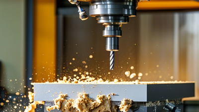
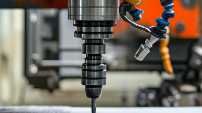
CNC cutting uses computer-controlled movement to remove material from a workpiece. The process begins with a digital CAD model. CAM software converts that model into toolpaths, speeds, and cutting movements. The machine then follows these instructions along multiple axes. A rotating tool, blade, or abrasive system shapes materials such as aluminum, steel, plastic, or wood.

In practical production, accuracy depends on more than software. Operators select suitable tools, secure the workpiece, and check machine calibration. A small setup error can shift a hole by a fraction of a millimeter. Sensors or probes may confirm the surface position before cutting begins. After machining, technicians measure critical features with gauges or coordinate measuring equipment. This inspection provides evidence that the part matches its drawing. It is not magic. Good results require controlled steps and experienced judgment.

Tips: Keep the material firmly clamped. Use sharp, application-matched tools. Review the toolpath before cutting. Watch for vibration, heat, and unusual noise. Measure the first completed part carefully. Even an efficient process may need adjustment when material hardness, tool wear, or humidity changes. That last point is often overlooked. A careful record of settings can make future production more reliable.
How CNC Cutting Achieves High Precision and Consistency

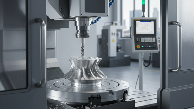
CNC cutting achieves precision through controlled movement, stable tooling, and carefully prepared digital instructions. Small errors matter. During production, the machine follows programmed toolpaths with consistent speed, depth, and direction. Operators still set work offsets, verify material thickness, and secure each sheet or workpiece before cutting. Proper clamping reduces vibration and prevents misplaced features.

High precision also depends on measurement. After the first cut, technicians inspect edges, holes, and critical dimensions with calipers, micrometers, or coordinate measuring equipment. These results can guide small program adjustments before the next batch. Tool wear may change cutting force, edge quality, or dimensional accuracy. Regular calibration helps detect this drift early. Data exposes problems.

Consistency requires more than software. Experienced operators record cutting speed, feed rate, tool condition, material batch, and inspection results. They watch for burrs, heat marks, warping, and uneven edges. A clean simulation cannot reveal every real-world issue. Material stress, temperature changes, or one loose clamp can still affect the final part. This is where practical judgment becomes important. CNC systems reduce variation, but they do not remove responsibility. Reviewing imperfect results often reveals process weaknesses that routine checks miss.

Why Choose CNC Cutting for Precision Manufacturing?

CNC cutting delivers accurate, repeatable results through computer-controlled toolpaths, stable machine motion, and consistent process parameters.

The chart compares representative upper-end dimensional tolerance values commonly associated with different CNC-based cutting and machining processes. Smaller values indicate tighter dimensional control. Actual results vary with material, machine condition, tooling, workpiece geometry, and inspection methods.

CNC Cutting Methods and Compatible Manufacturing Materials

CNC cutting turns digital measurements into repeatable physical parts. In precision manufacturing, method selection matters as much as machine accuracy. A router suits wood, plastics, and softer composites. A milling cutter handles aluminum, brass, steel, and engineered polymers. For flat sheet metal, laser cutting creates narrow kerfs and clean profiles. Waterjet cutting works well when heat could distort the material. It can also process stone, glass, rubber, and layered composites.

Each method leaves a different surface and edge condition. Laser energy may create a heat-affected zone on some alloys. Waterjet cutting avoids thermal stress, but abrasive management affects operating costs. Milling produces accurate pockets, holes, and three-dimensional features. Yet tool wear can change dimensions during long runs. Cutting speed, feed rate, material hardness, and thickness must be tested together. A reliable shop records these settings with inspection results, not memory.

I have seen a small setup mistake spoil an otherwise accurate batch. Clamping pressure, dust, vibration, or a dull tool can matter. No process is flawless. Experienced technicians inspect the first part before continuing production. Calipers, micrometers, and coordinate measurements verify critical features. Designers should allow realistic tolerances and avoid sharp internal corners when possible. Material certificates and traceable measurements strengthen reliability, although paperwork cannot replace practical testing. CNC cutting is powerful, but careful process judgment still decides whether the finished part truly fits.

How CNC Cutting Improves Production Efficiency

Why Choose CNC Cutting for Precision Manufacturing?

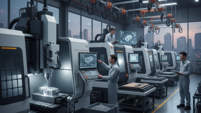
CNC cutting improves production efficiency by turning digital drawings into repeatable tool movements. A programmed machine can cut identical parts through multiple shifts, with fewer manual adjustments. Operators spend less time measuring edges, changing layouts, and correcting avoidable mistakes. That matters on a busy shop floor. A small setup error can delay an entire batch.

Deloitte’s 2024 Smart Manufacturing and Operations Survey reports that manufacturers using smart technologies commonly expect 10% to 20% gains in production output, productivity, and capacity. CNC cutting supports this direction by connecting design data, machining parameters, and inspection records. Automatic tool paths also shorten preparation time for recurring work. In practice, an operator can load a sheet, confirm the program, and monitor cutting while another task continues nearby. The result is not magic. Material thickness, tool wear, and poor programming still affect speed.

The U.S. National Institute of Standards and Technology emphasizes measurement, process control, and reliable digital manufacturing data. CNC equipment makes these controls easier to apply consistently. For example, a production team can compare a finished hole with its programmed diameter and adjust the next cycle. Scrap may fall. It may not, if the original drawing is wrong. That uncomfortable detail deserves attention. Efficiency depends on disciplined maintenance, accurate nesting, proper feed rates, and trained people. A fast machine with weak process control simply produces mistakes faster.

Key Factors for Choosing the Right CNC Cutting Process

Choosing CNC cutting begins with the material, not the machine. Aluminum, stainless steel, acrylic, and hardened steel react differently to heat and force. Define the required tolerance, edge quality, thickness, and production volume before selecting a process. Laser cutting suits thin sheets and detailed profiles. Waterjet cutting handles heat-sensitive materials with little thermal distortion. Plasma cutting can reduce costs on thicker steel, but its edge finish may need secondary work. Small details matter.

Review the part drawing and its tightest feature. A tolerance of ±0.05 mm requires different planning from a rough structural bracket. Consider kerf width, piercing marks, taper, burrs, and heat-affected zones. Ask how the part will be inspected. Calibrated gauges, coordinate measurement, and documented inspection records support reliable decisions. An experienced operator should also check nesting efficiency, fixture access, and toolpath stability. Saving material helps, but a crowded layout can slow production and increase rejects.

Cost should include setup, cutting time, finishing, inspection, and possible rework. Request a sample cut when surface quality or dimensional accuracy is uncertain. Examine the edge under normal lighting, then measure critical features. I have found that a fast first run can hide problems near corners and small holes. That lesson is easy to overlook. Leave room for design changes, especially when the drawing is still evolving. The right process balances accuracy, material behavior, delivery pressure, and repeatability instead of chasing the lowest quote.

Why Choose CNC Cutting for Precision Manufacturing? – Key Factors for Choosing the Right CNC Cutting Process

CNC Cutting Process Typical Materials Typical Maximum Material Thickness Typical Dimensional Tolerance Edge Characteristics Relative Cutting Speed Best Use Cases Key Selection Consideration
CNC Milling Aluminum, steel, stainless steel, brass, titanium, plastics, composites Determined mainly by tool reach, workholding, and machine travel; commonly used for parts up to approximately 100 mm in a single setup Approximately ±0.025 to ±0.125 mm for many production applications; tighter results require controlled conditions Good surface finish with accurate profiles, pockets, slots, and 3D contours Medium Complex prismatic parts, prototypes, molds, fixtures, and close-tolerance components Choose when geometry, multiple features, and dimensional accuracy are more important than simple sheet throughput
CNC Turning Steel, stainless steel, aluminum, brass, titanium, engineering plastics Commonly suitable for round stock and bars up to approximately 300 mm in diameter, depending on machine capacity Approximately ±0.025 to ±0.075 mm for many well-controlled operations Excellent cylindrical accuracy; grooves, threads, tapers, and bores can be produced in one setup High for rotational parts Shafts, bushings, pins, threaded parts, bearing seats, and other axisymmetric components Choose when the workpiece is primarily rotational and concentricity is a major requirement
CNC Laser Cutting Mild steel, stainless steel, aluminum, brass, copper, and selected non-metallic sheet materials Approximately 0.5–25 mm for common industrial sheet and plate applications; capacity varies by laser power and material Approximately ±0.05 to ±0.20 mm for thin and medium sheet applications Narrow kerf, low mechanical force, and generally clean edges; heat-affected zones may occur High for thin sheet and repeated profiles Flat-sheet profiles, detailed contours, nesting jobs, and high-volume 2D production Choose for intricate 2D shapes, fast sheet processing, and minimal cutting-force distortion
CNC Plasma Cutting Mild steel, stainless steel, and aluminum Approximately 1–50 mm for common production equipment; heavy-duty systems can cut thicker plate Approximately ±0.25 to ±1.00 mm, depending on thickness, consumables, speed, and machine setup Fast cutting with a visible heat-affected zone and more taper than laser or waterjet cutting Very high for medium and thick conductive plate Structural parts, brackets, frames, heavy plate, and applications where throughput is more important than fine edge quality Choose for conductive metals and thicker stock when cost and speed outweigh ultra-fine detail
CNC Waterjet Cutting Metals, stone, glass, ceramics, rubber, composites, and layered materials Approximately 1–150 mm or more, depending on material type, abrasive system, and machine capability Approximately ±0.05 to ±0.20 mm for many precision applications; taper compensation improves accuracy No heat-affected zone; edges may show slight taper or striation depending on speed and quality setting Low to medium Heat-sensitive materials, thick plate, mixed-material projects, and difficult-to-machine materials Choose when thermal distortion must be avoided or when the material is not suitable for thermal cutting
CNC Router Cutting Wood, MDF, plastics, foam, aluminum sheet, and composite panels Approximately 3–100 mm, depending on spindle power, tooling, and workholding Approximately ±0.10 to ±0.50 mm for common routing applications Clean profiles in non-metallic materials; tool marks and burrs depend on feed rate and cutter selection High for sheet and panel work Cabinet components, signage, panels, foam models, plastic parts, and light aluminum work Choose for large-format sheet processing and non-metallic materials requiring flexible routing or engraving
CNC EDM Electrically conductive hardened steels, carbide, nickel alloys, and titanium Typically used for smaller or medium-sized features; thickness is limited by electrode, wire, and machine travel Approximately ±0.005 to ±0.025 mm for precision wire EDM applications Very precise and burr-free; surface texture depends on the number of finishing passes Low Hardened materials, fine slots, intricate punches, dies, and geometries that conventional tools cannot reach Choose when extreme accuracy or complex internal profiles are required in conductive, hardened materials

Note: Values are representative industrial ranges rather than guaranteed specifications. Actual results depend on machine rigidity, material condition, tool selection, workholding, programming, cutting parameters, thermal control, and inspection method.