How to Choose the Best CNC Vertical Milling Machine
Choosing the right cnc vertical milling machine can shape a shop’s accuracy, output, and operating costs for years. The decision is practical, not just technical. A heavy cast-iron frame, a rigid spindle, and a well-matched tool changer matter when cutting steel or running long jobs. So do floor space, service access, and operator experience. Small details count.
Grand View Research estimated the global CNC machine market at USD 83.99 billion in 2023 and projected 6.3% annual growth from 2024 to 2030. That report covers CNC machines broadly, not vertical mills alone. Still, it signals continued investment in automated machining. Growth is not a buying recommendation. A machine that suits a high-volume plant may burden a small job shop with unnecessary cost.
A useful starting point is process discipline. Toyota Production System architect Taiichi Ohno is often quoted: “Without standards, there can be no improvement.” Apply that idea to machine selection: define materials, part dimensions, tolerances, batch sizes, and expected spindle hours before comparing models. Then examine spindle power and speed, axis travel, control features, tool capacity, and local technical support. Ask suppliers for a test cut using a representative part. Inspect the finish, measure repeatability, and review cycle time. Do not rely on brochure numbers alone. They can look convincing.
There is no perfect machine for every shop. A careful shortlist—and a few uncomfortable questions about future work—can prevent an expensive mismatch.
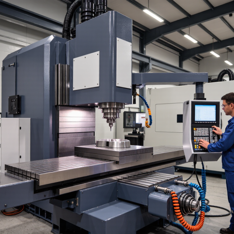
Define Vertical Milling Configurations: 3-Axis XYZ, 4th-Axis, and 5-Axis
Choosing a vertical mill starts with the part, not the axis count.
A 3-axis XYZ machine moves the tool along three linear directions. It suits flat plates, pockets, drilled patterns, and many prismatic parts. Picture a vise-held block: the operator can machine its top face, but may need to reposition it for side features. That setup takes time and can introduce alignment errors. It is often the sensible choice for repeatable work with limited angled surfaces.
A fourth-axis rotary table turns the workpiece around one axis, allowing features around a shaft or several sides of a component to be cut with fewer manual changes. Check table capacity, fixture clearance, and whether the rotary unit can index or move continuously. Five-axis machines add two rotational axes, letting the tool approach complex surfaces from changing angles. They can reduce setups, but programming, collision checks, and operator training become more demanding.
More axes are not automatically better.
Grand View Research estimated the global CNC machine market at USD 83.99 billion in 2023 and projected 5.3% annual growth through 2030; that market-wide estimate does not identify a preferred axis configuration. Before choosing, compare actual part drawings, tolerance requirements, batch sizes, and setup hours. One awkward fixture can change the calculation.
Size the Work Envelope by X/Y/Z Travel, Table Load, and Part Dimensions
Start with the part’s largest finished dimensions, then allow room for the cutter, holder, and approach path. A 600 mm panel does not necessarily fit a machine with 600 mm of X travel. The tool may need to move beyond an edge, while clamps can block that route. Check X and Y travel against the actual setup, not just the part drawing. For Z, include the part height, fixture or vise height, tool length, and safe clearance. A tall vise can consume more vertical room than expected. Small details matter.
Table load should include the part, vise, fixture plate, and any rotary unit—not just the workpiece. Check the machine’s specified load limit and how the weight will sit on the table; a heavy, off-center setup may behave differently from an evenly distributed load. One planning mistake is choosing a machine from the largest part alone. It is easy to overlook setup space, especially when dimensions come from an early drawing. Measure the intended fixture, and confirm travel and load figures in the machine specifications. Leave practical clearance where possible, but avoid assuming that extra capacity solves every access problem. Recheck the setup after tooling is selected.
How to Choose the Best CNC Vertical Milling Machine — Size the Work Envelope by X/Y/Z Travel, Table Load, and Part Dimensions
| Machine Size Class |
Typical X/Y/Z Travel |
Typical Table Size |
Typical Maximum Table Load |
Practical Part Size to Evaluate |
Best Suited For |
| Compact |
500 × 400 × 400 mm
(19.7 × 15.7 × 15.7 in) |
700 × 400 mm
(27.6 × 15.7 in) |
About 300 kg
(660 lb) |
Up to about 350 × 250 × 250 mm
(13.8 × 9.8 × 9.8 in) |
Small fixtures, precision components, and limited-floor-space workshops |
| Mid-size |
800 × 500 × 500 mm
(31.5 × 19.7 × 19.7 in) |
1,000 × 500 mm
(39.4 × 19.7 in) |
About 600 kg
(1,320 lb) |
Up to about 600 × 350 × 350 mm
(23.6 × 13.8 × 13.8 in) |
General job-shop work, moderate-size plates, housings, and production parts |
| Large |
1,300 × 700 × 650 mm
(51.2 × 27.6 × 25.6 in) |
1,400 × 700 mm
(55.1 × 27.6 in) |
About 1,200 kg
(2,645 lb) |
Up to about 1,000 × 550 × 450 mm
(39.4 × 21.7 × 17.7 in) |
Larger components, heavy fixtures, and parts requiring more setup clearance |
| Extra-large |
2,000 × 800 × 700 mm
(78.7 × 31.5 × 27.6 in) |
2,200 × 800 mm
(86.6 × 31.5 in) |
About 2,000 kg
(4,410 lb) |
Up to about 1,600 × 650 × 500 mm
(63.0 × 25.6 × 19.7 in) |
Long or heavy workpieces, large molds, and applications needing extended X travel |
Selection note: These figures are illustrative sizing ranges, not specifications for a particular machine. Allow room for the vise or fixture, tool approach, clamps, and safe tool changes. Confirm the machine’s actual travel, table-load rating, spindle-to-table clearance, and permissible load distribution with its technical documentation before purchase.
Match Spindle Speed (6,000–24,000 rpm) and BT30, BT40, or BT50 Taper
Choosing between 6,000 and 24,000 rpm starts with cutter diameter and material, not the largest number on the specification sheet. Small end mills often benefit from higher speeds in aluminum or plastics, provided feed rate, rigidity, and chip removal are suitable. Larger cutters and tough steels usually need lower rpm and stronger torque. Check the spindle’s torque curve; a machine may reach 18,000 rpm yet feel weak at the speeds your work actually requires. That distinction matters.
BT30, BT40, and BT50 describe taper sizes, not a simple quality ranking. BT30 suits lighter cuts, smaller tools, and compact work, often alongside faster spindles. BT40 is a practical middle ground for mixed jobs and general production. BT50 supports heavier tooling and higher cutting loads, though greater tool mass can limit acceleration and high-speed use. Fit matters, too. Check each toolholder’s rated speed and balance before running it near the spindle’s maximum.
Match the taper to actual cuts: a 10 mm end mill in aluminum rarely needs the setup used for a 50 mm face mill in steel. Compare spindle power, tool-change limits, and coolant delivery as well. A larger taper can feel reassuring, but it may add cost and inertia without helping small-tool work. It is easy to overvalue rpm. I would verify sample-cut data, since catalog figures cannot show chatter, surface finish, or sustained torque. That check can change the decision.
Check Positioning Accuracy and Repeatability Under ISO 230-2
How to Choose the Best CNC Vertical Milling Machine
Check Positioning Accuracy and Repeatability Under ISO 230-2
A machine’s axis specifications deserve more than a quick glance. ISO 230-2 describes methods for testing the positioning accuracy and repeatability of numerically controlled axes. Ask for the actual test results, not only a brochure figure. Check which axis, travel range, and measurement conditions the results cover.
Look for measurements taken in both travel directions. Backlash, thermal changes, and mechanical behavior can make an axis approach the same coordinate differently from opposite directions. Repeatability shows how closely it returns to a commanded position across repeated attempts; accuracy indicates how near the measured position is to the target. Small differences matter. A few microns may affect a tight bore or a row of aligned holes.
Ask whether testing used a calibrated measuring system and whether the report states environmental conditions. Then compare the tested travel with your own work zone. A strong result over a short central section may not describe performance near the ends of the axis. I would still want a practical cutting trial with representative tooling and material. The standard test is useful, but it cannot reproduce every shop condition. That distinction is easy to overlook.
Compare Tool Capacity, Automation Options, and Cost per Finished Part
A CNC vertical milling machine should be judged by the parts it can finish, not just its advertised travel.
Start with the tools your jobs actually require. A small tool magazine may suit short runs, but frequent tool changes can interrupt production. For a component needing a face mill, several end mills, and a drill, count every tool and leave room for likely variations. Too much capacity can also mean paying for space that stays unused. That matters.
Automation changes the calculation. A tool changer reduces manual pauses, while a pallet system may keep one job cutting as another is prepared. These options help most when setups repeat or operators manage several machines. For changing, low-volume work, added automation may not recover its cost. Track actual setup minutes and unattended cutting time over a representative week; estimates made on a quiet day can mislead.
Compare cost per finished part, not purchase price alone. Include tooling, labor, energy, maintenance, scrap, and time spent correcting setups. Divide those costs by parts that pass inspection, not merely parts produced. A machine that cuts faster may still lose if it creates more rework. The math is rarely perfect. Record assumptions, then revisit them after production begins. A few measured jobs will reveal more than a polished quotation.