What Is LEVIL CNC and How Does It Work?

What is levil cnc, and how does it work? The answer begins with controlled movement, not mysterious automation. A CNC system converts digital instructions into precise motion across multiple axes. Its controller directs motors, while the spindle removes material from a workpiece. Cutting tools, feeds, speeds, and workholding determine the final result. Small errors can still become visible. A loose fixture may leave chatter marks across an aluminum panel.

Industry forecasts show strong demand for computer numerical control equipment. Grand View Research valued the global CNC machine market at approximately USD 83.4 billion in 2023. Fortune Business Insights reported a different estimate, showing why market figures require careful comparison. Their forecasts also point toward continued growth through automation, aerospace production, medical components, and general manufacturing. These figures describe the broader CNC market, not levil cnc specifically.

Professor Yoram Koren, a recognized manufacturing systems researcher, has emphasized that “automation must be designed around the manufacturing process.” That principle explains how levil cnc should be evaluated. Look beyond advertised accuracy. Examine axis travel, spindle power, software compatibility, calibration procedures, and operator training. The machine may appear simple. Its performance depends on disciplined setup and verified toolpaths.

In practical use, an operator loads a CAD/CAM program, secures the stock, sets the tool offset, and runs a controlled cycle. Sensors and feedback can reduce mistakes, but they cannot replace judgment. This is where many explanations become too confident. Actual results vary with material, maintenance, tooling, and experience. A reliable evaluation must test the machine under realistic workshop conditions.

What Is LEVIL CNC and How Does It Work?

What Is LEVIL CNC and What Is It Used For?

A CNC system is a computer-controlled machine used to shape wood, plastic, foam, and selected metals. It follows digital instructions called G-code. These instructions control movement, cutting speed, depth, and tool changes. The operator first creates a design in CAD software. CAM software then converts that design into machining paths.

The machine moves a cutting tool along several axes. A flat sheet can become a sign, cabinet panel, prototype, or precision component. In a workshop, the tool may carve a shallow groove, drill mounting holes, or cut a smooth outer profile. Vacuum tables or clamps hold the material firmly during cutting. This matters because even slight movement can ruin accurate work.

CNC equipment is useful for repeated production. Each pass can follow the same programmed dimensions. It also helps makers produce complex shapes that would take longer by hand. Still, automation does not remove responsibility. The operator must select a suitable bit, secure the workpiece, and check the cutting path. A wrong feed rate may burn wood or break a tool. I have found that test cuts save time, although they can feel unnecessary. Measurements also deserve a second check. Small design errors often become expensive after machining begins.

What Are the Main Components of a LEVIL CNC Machine?

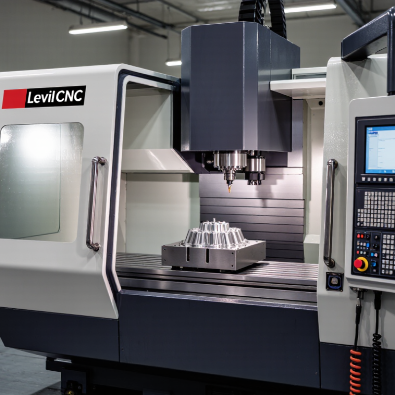
A LEVIL CNC machine uses computer-controlled motion to cut, drill, or shape material with measured accuracy. Its main structure is the frame, which supports every moving part. A rigid frame reduces vibration during cutting. The worktable holds the material in place, often with clamps, fixtures, or vacuum support. Even a small movement can affect the finished edge.

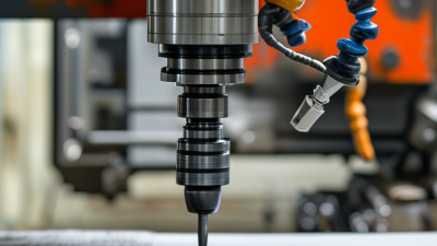
The motion system includes guide rails, carriages, and drive mechanisms such as ball screws or rack-and-pinion units. These parts move the cutting tool along the X, Y, and Z axes. Motors receive signals from the controller and convert them into precise movement. The spindle provides rotary power, while a collet or chuck secures the cutting tool. Heat, dust, and worn bearings can reduce accuracy over time. Maintenance matters.

The controller acts as the machine’s operating center. It reads programmed toolpaths and coordinates motor speed, position, and cutting actions. Sensors may monitor travel limits, tool position, or emergency conditions. A cooling system can control heat during demanding work. Not every setup performs perfectly. Poor calibration, loose fixtures, or an incorrect tool offset can spoil an otherwise sound program. In practical use, operators should check alignment, tool condition, and sample cuts before full production. A simple test piece often reveals problems that software cannot.

What Is LEVIL CNC and How Does It Work? - What Are the Main Components of a LEVIL CNC Machine?

A CNC machine uses computer-controlled motion to remove material from a workpiece according to programmed toolpaths. The table below summarizes the main components, their functions, typical specifications, and roles in the machining process.

Component or Data Dimension Main Function Typical Technical Characteristics How It Works in the CNC Process Important Considerations
CNC Controller Reads the programmed instructions and coordinates machine movements. Common inputs: G-code, M-code, tool offsets, work offsets, and sensor feedback. Converts programmed coordinates into commands for the drive motors, spindle, coolant system, and auxiliary functions. Controller accuracy, processing speed, memory capacity, and compatibility with standard programming codes affect machine performance.
Machine Frame and Base Supports the machine and absorbs cutting forces and vibration. Typical materials: cast iron, fabricated steel, or polymer concrete. A rigid base is essential for dimensional stability. Maintains the relative position of the spindle, worktable, and linear guideways while cutting forces are applied. High rigidity helps reduce chatter, surface defects, tool wear, and dimensional errors.
Spindle and Spindle Motor Rotates the cutting tool or workpiece at a controlled speed. Typical speed range: approximately 6,000–24,000 rpm for many machining applications. Power commonly ranges from about 1.5–30 kW, depending on machine size and use. The controller sets spindle speed and rotation direction. The motor transfers torque through the spindle to the tool holder. Maximum speed, available torque, runout, cooling method, and tool-holding system must match the material and cutting operation.
Cutting Tool and Tool Holder Removes material from the workpiece and maintains the tool in the spindle. Common tools: end mills, drills, face mills, reamers, and inserts. Tool materials include high-speed steel, carbide, and coated carbide. The tool follows a programmed path while spindle rotation and feed motion produce the required cut. Tool diameter, flute count, cutting length, tool material, and proper clamping influence accuracy and tool life.
Linear Guideways Guide the table, saddle, or spindle along the machine axes. Common types: recirculating ball guides and box ways. Travel accuracy is commonly specified in micrometres per metre. Allow smooth, constrained movement along the X, Y, and Z axes while resisting side loads and cutting forces. Correct lubrication, preload, alignment, and protection from chips are important for long-term accuracy.
Ball Screws or Linear Drive System Converts motor rotation into precise linear movement. Typical ball-screw lead: approximately 5–20 mm per revolution, depending on axis design and required speed. Servo or stepper motors rotate the screw, and the ball nut moves the machine component to the commanded position. Backlash, preload, thermal expansion, lubrication, and screw alignment directly affect positioning accuracy.
Servo or Stepper Drive Motors Move and control the machine axes. Typical controlled axes: three linear axes labeled X, Y, and Z; advanced machines may include rotary axes. The controller sends position and speed commands to the drives, which regulate motor movement through feedback or programmed step signals. Servo systems generally provide closed-loop feedback, while stepper systems are simpler and may be more vulnerable to missed steps under overload.
Position Feedback System Measures actual axis or spindle position and reports it to the controller. Common devices: rotary encoders, linear scales, proximity sensors, and home switches. Feedback allows the control system to compare commanded position with actual position and correct motion errors. Resolution, repeatability, contamination protection, and correct calibration are important for precision machining.
Worktable and Fixture Supports and secures the workpiece during machining. Common fixtures: vises, clamps, modular fixtures, vacuum tables, and dedicated jigs. The workpiece is positioned relative to the machine coordinate system, then held firmly while the tool performs programmed movements. Clamping force must prevent movement without deforming the workpiece. Poor fixturing can cause vibration and inaccurate dimensions.
Coolant and Chip Management System Controls cutting temperature, lubricates the cutting zone, and removes chips. Typical methods: flood coolant, mist, air blast, through-tool coolant, chip trays, and chip conveyors. Coolant is directed toward the cutting area while chips are collected or transported away from the work zone. Coolant concentration, filtration, flow rate, chip evacuation, and operator safety must be monitored.
Electrical Cabinet and Power Supply Distributes electrical power and protects the control, drive, and auxiliary circuits. Includes: circuit breakers, contactors, servo drives, control boards, transformers, and cooling or ventilation components. Provides regulated power to the controller, motors, spindle drive, sensors, lighting, pumps, and safety circuits. Proper grounding, thermal management, electrical protection, and routine inspection help prevent downtime and equipment damage.
Machine Enclosure and Safety System Contains chips and coolant and protects the operator from moving parts. Typical safety features: interlocked doors, emergency-stop buttons, guards, warning indicators, and protective windows. The safety system can stop or inhibit machine operation when a door is opened, an emergency stop is pressed, or an unsafe condition is detected. Safety interlocks should never be bypassed. Operators should use appropriate eye, hearing, and personal protective equipment.
CAD/CAM and G-Code Program Defines the geometry, cutting strategy, toolpath, speeds, feeds, and machine commands. Typical programming data: coordinates, feed rate, spindle speed, tool number, coolant commands, and work offsets. CAD models are converted into CAM toolpaths, post-processed into machine-readable code, and executed by the CNC controller. Simulation, dry runs, toolpath verification, correct work offsets, and collision checks reduce programming and setup errors.
Typical Operating Sequence Describes the general workflow from digital design to finished part. Basic sequence: design, process planning, setup, zeroing, tool loading, machining, inspection, and correction. The operator secures the workpiece, establishes coordinate zero, loads tools, verifies the program, runs the machining cycle, and checks the finished dimensions. Accurate setup, appropriate cutting parameters, tool condition, and in-process inspection are essential for consistent results.
Note: Technical values shown in this table are representative ranges for general CNC machining equipment. Actual travel, speed, power, accuracy, and load capacity depend on the machine design, configuration, material, tooling, and application.

How Does the LEVIL CNC Machining Process Work?

The LEVIL CNC machining process begins with a 3D CAD model. Engineers convert that model into toolpaths using CAM software. The control system then translates coded instructions into precise movements. Cutting tools remove material from metal, plastic, or composite stock. Spindles rotate at programmed speeds, while feed rates control cutting pressure. Coolant reduces heat and carries chips away from the work area.

Accuracy depends on more than software. Operators must secure the workpiece, set the tool length, and check the machine coordinate system. A small setup error can create visible steps on a milled surface. In practical production, a perfect first pass is uncommon. Trial cuts and inspection still matter. The World Robotics 2024 report recorded 541,302 industrial robot installations worldwide in 2023, showing how automation is expanding around machining operations. Deloitte’s 2023 Smart Manufacturing survey also found that 86% of manufacturers considered smart factory investment important for future competitiveness.

Tips: Use a sharp tool, stable fixturing, and conservative cutting parameters. Measure critical features after roughing and finishing. Do not rely only on the machine display. A calibrated micrometer can reveal problems early. Review chip shape, surface marks, and tool wear. These details often expose heat, vibration, or incorrect feed settings before scrap increases.

Which Materials and Operations Can LEVIL CNC Handle?

LEVIL CNC refers to a computer-controlled machining workflow that converts digital drawings into precise cutting movements. Its practical strength is material flexibility. Aluminum cuts quickly and suits lightweight housings, brackets, and prototypes. Mild steel supports stronger fixtures, while stainless steel demands slower speeds and effective coolant. Brass and copper machine cleanly, but copper can produce troublesome heat and burrs. Engineering plastics, including nylon and POM, are also workable with sharp tools and controlled clamping.

Typical operations include facing, slotting, pocketing, drilling, tapping, boring, contouring, and engraving. Three-axis machines handle many flat components. Four- and five-axis systems reach angled surfaces and reduce repeated setups. According to the 2024 U.S. Cutting Tool Consumption Report, American cutting-tool consumption reached approximately 2.56 billion dollars in 2023. That figure reflects a practical reality: tooling choices strongly influence cost, finish, and productivity. A cheaper cutter may become expensive after one damaged edge.

Industry automation is expanding too. The International Federation of Robotics reported 4.28 million industrial robots operating worldwide in 2023. CNC machining benefits from this connected environment, especially during repeat production. Still, material hardness, part geometry, and workholding remain decisive. CNC cannot magically cut everything. Hardened alloys, ceramics, and composites may require specialized abrasives, tooling, or processes. I would always test a small sample first. Even a correct toolpath can fail when vibration, heat, or clamping pressure is underestimated.

What Factors Affect LEVIL CNC Performance and Accuracy?

A LEVIL CNC system removes material through programmed movements across multiple axes. Its performance depends on how accurately those movements remain controlled under real cutting loads. The machine may appear rigid, yet vibration can develop when speed, feed rate, tool length, and material hardness do not match.

Thermal stability is often underestimated. Steel expands about 11.7 micrometres per metre per °C, according to commonly used NIST material-property data. A 500 mm axis can therefore shift nearly 6 micrometres after a 1°C rise. Spindle heat, motors, coolant temperature, and workshop airflow all matter. ISO 230-3 specifically addresses thermal behaviour in machine tools. Skipping warm-up cycles can make a good calibration look unreliable.

Mechanical condition also controls accuracy. Backlash, guideway wear, loose workholding, tool deflection, and contaminated surfaces can create visible dimensional errors. ISO 230-2 evaluates positioning accuracy and repeatability statistically, rather than relying on one impressive tolerance figure. In practical inspections, I would compare three repeated measurements at different positions, then check the result after the machine reaches operating temperature. This exposes drift that a single test can miss. Cutting data deserves equal attention. Excessive feed increases force; excessive speed may raise heat. The correct setting is not always the manufacturer’s first recommendation. A 2023 manufacturing outlook from Deloitte identifies skills, maintenance, and process control as continuing productivity challenges, and CNC accuracy reflects all three. Calibration helps, but it cannot compensate for a weak fixture or a dull tool.