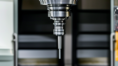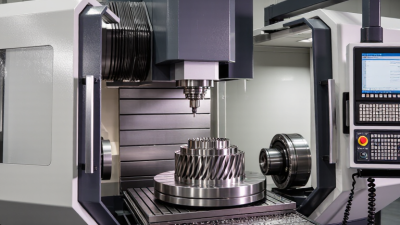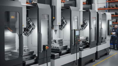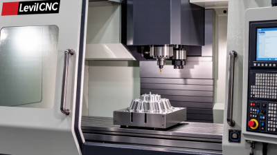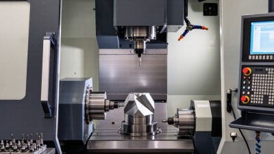
A 5 axis milling machine moves a cutting tool along three linear axes and two rotational axes. This motion allows the tool to approach complex surfaces from changing angles. It can machine turbine blades, medical implants, molds, and aerospace brackets with fewer setups.
Professor Yusuf Altintas, a leading authority in machining science, explains the practical goal this way: “The cutting tool should reach the surface from the best direction.” That idea defines five-axis work. A tilted tool can maintain better contact with a curved surface. It can also reduce awkward fixtures and repeated repositioning. Fewer setups may improve accuracy, consistency, and production time.
The machine is not automatically better.
Successful operation depends on programming, tool selection, machine calibration, and operator judgment. A small collision near a rotary axis can damage an expensive spindle. Poor tool orientation can leave marks across a polished mold. Even experienced teams sometimes choose five-axis machining when three-axis methods would be simpler and cheaper.
This guide examines what a 5 axis milling machine is, how its axes work, and where it creates real value. It also considers limitations, including software complexity, training demands, and higher equipment costs. The details matter. A machine turning smoothly around a fixture looks impressive, but performance must be measured through tolerances, surface finish, cycle time, and repeatability.
The technology is powerful. It is not magic.
What Is a 5 Axis Milling Machine?
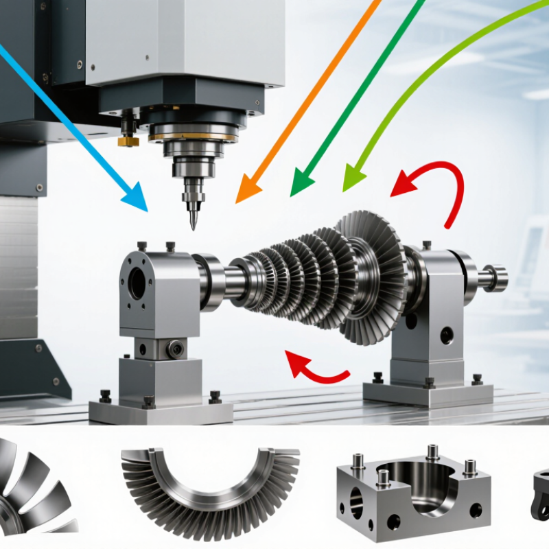
A 5-axis milling machine removes material while moving a cutting tool across five coordinated directions. Three linear axes control left-right, front-back, and vertical movement. Two rotary axes tilt or rotate the workpiece. This arrangement lets the cutter reach angled surfaces, deep cavities, and curved edges without repeated repositioning.
Its core purpose is accuracy with fewer setups. In practical machining, one fixture can replace several manual alignments. That reduces locating errors and keeps complex features related to one datum. It also allows shorter tools in many applications, improving rigidity and surface quality. The result is often valuable for aerospace, medical, energy, and precision mold components. Still, five axes do not automatically guarantee better parts. Poor post-processing or weak workholding can erase the advantage.
Industry data shows why this technology attracts investment. Grand View Research valued the global CNC machine market at about USD 83.6 billion in 2023 and projected continued growth through 2030. Fortune Business Insights also reports strong expansion in the five-axis CNC machine segment, driven by complex-part production and automation. These figures are forecasts, not shop-floor promises. Actual gains depend on programming skill, toolpath verification, machine calibration, and operator experience. A first-time user may even produce slower results. That is the uncomfortable part. Five-axis machining is powerful, but it is not a shortcut around manufacturing discipline.
| Dimension | Data / Definition | Core Purpose and Practical Meaning |
|---|---|---|
| Basic Definition | A 5-axis milling machine can move a cutting tool or workpiece along three linear axes and around two additional rotary axes. | It can approach a component from multiple directions during one setup, enabling the production of complex three-dimensional geometries. |
| Linear Axis X | Provides straight-line movement from left to right, depending on the machine coordinate system. | Controls one primary horizontal direction and contributes to the tool’s positioning across the work envelope. |
| Linear Axis Y | Provides straight-line movement along the second horizontal direction. | Positions the tool or workpiece across the depth of the machining area. |
| Linear Axis Z | Provides straight-line movement along the vertical or spindle direction. | Controls cutting depth, tool engagement, and movement toward or away from the workpiece. |
| Rotary Axis A | Rotates around the X axis. | Tilts the tool or workpiece to reach angled surfaces and improve access to difficult features. |
| Rotary Axis B | Rotates around the Y axis. | Provides a second orientation change, allowing the cutting tool to maintain a suitable angle against complex surfaces. |
| Five-Axis Motion | The three linear axes and two rotary axes can be coordinated by the machine control system. | Coordinated motion supports simultaneous multi-axis cutting, rather than limiting machining to separate straight-line movements. |
| 3+2 Machining | The rotary axes first position the workpiece or tool, while the three linear axes perform the cutting operation. | This method simplifies the machining of multiple angled faces and can reduce the number of fixtures or setups required. |
| Simultaneous 5-Axis Machining | All five axes move in a coordinated manner while the cutter remains engaged with the workpiece. | It is suited to sculptured surfaces, compound angles, and parts that require continuous tool-orientation changes. |
| Main Manufacturing Benefit | More surfaces can be machined in a single setup compared with many three-axis processes. | Fewer setups can reduce repositioning errors, setup time, and the need for specialized fixtures. |
| Surface-Finish Potential | The cutter can be oriented to maintain a more favorable contact angle with certain curved surfaces. | Improved tool orientation can reduce excessive tool engagement and support more consistent surface finish when programming and tooling are appropriate. |
| Geometric Capability | Suitable for undercuts, deep cavities, inclined planes, impellers, turbine-style blades, molds, and other complex profiles. | Rotary positioning expands tool access beyond the fixed orientations available on a conventional three-axis machine. |
| Accuracy Consideration | Accuracy depends on machine construction, rotary-axis calibration, thermal control, workholding, tooling, and programming. | Having five axes does not automatically guarantee higher accuracy; the complete machining system must be properly calibrated and controlled. |
| Programming Requirement | Five-axis work generally requires suitable CAM software, post-processing, collision checking, and machine-tool kinematic information. | Tool paths must account for rotary-axis limits, tool orientation, fixtures, machine collisions, and safe transition movements. |
| Typical Workpiece Materials | Common materials include aluminum alloys, steels, stainless steels, titanium alloys, nickel-based alloys, plastics, and composites. | Material selection depends on the component design, cutting-tool system, machine rigidity, spindle capability, and required production conditions. |
| Typical Applications | Aerospace components, medical implants, automotive prototypes, energy components, precision molds, dies, and complex general-machining parts. | These applications benefit from multi-sided access, complex surface generation, and reduced workpiece repositioning. |
| Key Limitation | The machine, tooling, programming, inspection, and operator requirements are generally more complex than those of three-axis machining. | Higher capability can involve greater purchase, maintenance, training, programming, and process-validation demands. |
| Core Purpose | To produce complex parts efficiently by combining three-dimensional linear positioning with two-axis rotary positioning. | The central objective is to improve tool access, reduce setups, support complex geometry, and achieve consistent machining results within the machine’s capabilities. |