What Is Axis CNC and How Does It Work?

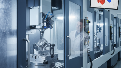
Axis CNC refers to computer numerical control machining that moves a cutting tool along defined directions. These directions are called axes. A typical three-axis CNC machine uses X, Y, and Z movements to shape metal, plastic, or wood. More advanced machines add rotary axes, allowing tools to reach angled surfaces without repeated manual repositioning.

The process begins with a digital design and manufacturing plan. CAM software converts the model into toolpaths, then produces G-code for the CNC controller. The controller reads each command and sends signals to motors, drives, and sensors. The spindle rotates the cutting tool, while linear guides move the workpiece or tool with measured precision. In a workshop, an operator may check tool diameter, set the work offset, and confirm the first cut with a micrometer.

Small errors matter.

Axis CNC is not simply automatic cutting. Material type, tool geometry, feed rate, spindle speed, and machine rigidity all influence the result. A qualified machinist reviews simulations and performs a controlled test before full production. This approach reflects practical experience and established manufacturing principles, rather than relying on software alone.

The explanation is not complete without mentioning limitations. A three-axis machine may struggle with deep cavities or complex curves. A five-axis system can improve access, but it demands stronger programming knowledge and careful collision control. Understanding how each axis moves helps users select suitable equipment, interpret machining data, and identify problems before they become expensive. It may sound straightforward, yet real accuracy depends on disciplined setup and repeated verification.
What Is Axis CNC and How Does It Work?

What Axis CNC Means and What Its Coordinate Axes Control

What Is Axis CNC and How Does It Work?

What Axis CNC Means and What Its Coordinate Axes Control

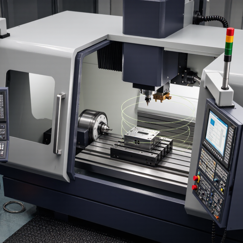
Axis CNC describes the directions a computer-controlled machine can move and coordinate. The standard three-axis system uses X, Y, and Z. X usually moves left and right. Y moves forward and backward. Z moves vertically, often along the spindle.

These movements guide the cutting tool through programmed coordinates. A machinist may set X0, Y0, and Z0 on a workpiece corner or selected reference point. The machine then follows numerical positions from that origin. Tool length compensation adjusts the Z position when tools have different lengths. Small errors here can damage the surface or leave excess material.

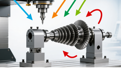
More advanced machines add rotary axes. A, B, and C rotate around the X, Y, and Z axes. A rotary axis can tilt or turn a part, allowing the tool to reach angled surfaces. However, axis labels can vary between machine designs, so operators should verify the manual and control display. This detail is easy to overlook.

In real setup work, coordinate confusion causes many avoidable mistakes. Machine zero, work offset, and tool position are not the same reference. A careful operator checks each value with a dry run, measured clearance, and controlled feed rate. Even experienced users can misread a sign or enter the wrong offset. That is why reliable production depends on both programmed logic and physical verification.

What Is Axis CNC and How Does It Work?

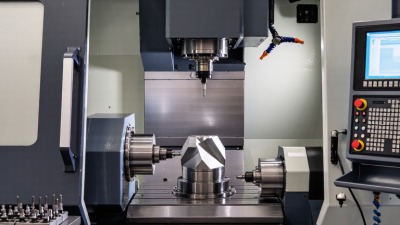
CNC axes describe the controlled directions in which a machine tool moves. X, Y, and Z are linear axes, while A, B, and C are rotary axes rotating around X, Y, and Z. A machine’s axis configuration determines how many directions it can control during machining.

The chart shows common CNC configurations: a basic turning machine typically uses two linear axes, a standard milling machine uses three linear axes, and advanced four- and five-axis machines add rotary axes.

Core Components That Make an Axis CNC Machine Operate

What Is Axis CNC and How Does It Work?

Core Components That Make an Axis CNC Machine Operate

An axis CNC machine removes material through controlled movement along defined directions. Its frame supports the cutting forces, while linear guides keep each axis moving smoothly. Ball screws or drive systems convert motor rotation into accurate table or spindle movement. Even small alignment errors can leave visible marks on a finished surface.

The controller reads programmed coordinates and sends signals to servo or stepper motors. Motor drives regulate speed, position, and torque during each move. A spindle supplies cutting power, while a tool holder keeps the cutter secure. Sensors may confirm home positions, limits, and safety conditions. Workholding is equally important because a loose part can ruin accuracy quickly. In real workshops, vibration and heat often expose weaknesses that looked minor during setup.

Tips: Check guideways, tool runout, and workholding before cutting. Keep cables away from chips and moving parts. A test pass in scrap material can reveal incorrect offsets. Do not trust perfect results immediately. Measure them.

The control software connects these components through machine instructions. It defines feed rate, spindle speed, depth, and toolpath direction. Coolant or air may reduce heat and clear chips, depending on the material. However, more coolant does not always mean better machining. Poor chip removal, weak clamping, or blunt tools can still damage the workpiece. Operators should compare the programmed position with actual measurements, especially after tool changes or maintenance. The machine performs the motion, but careful setup determines whether that motion becomes reliable work.

What Is Axis CNC and How Does It Work?

Core Components That Make an Axis CNC Machine Operate

Component or Axis Primary Function How It Works Typical Technical Data Role in the Machining Process
X Axis Provides horizontal linear movement from left to right. A servo or stepper motor drives a ball screw, rack-and-pinion system, or linear motor to position the machine slide. Linear travel; commonly several hundred millimetres to more than 1 metre, depending on machine size. Controls the tool position across the workpiece width.
Y Axis Provides horizontal movement from front to back. The axis drive converts programmed electrical commands into controlled mechanical movement along the Y direction. Travel range varies by machine design; often similar to or smaller than the X-axis travel. Controls depth and front-to-back positioning during cutting.
Z Axis Provides vertical movement between the cutting tool and workpiece. A motor-driven screw or linear drive moves the spindle, tool head, or table vertically. Travel must accommodate tool length, workholding, and the required cutting depth. Sets cutting depth, clearance height, and vertical approach movements.
Rotary A, B, and C Axes Rotate the workpiece or cutting tool around the X, Y, and Z axes. Rotary tables, tilting heads, or integrated rotary units use geared or direct-drive motors for angular positioning. A full rotation is 360°; multi-axis machines may provide continuous or indexed rotary movement. Enables machining of angled surfaces, complex contours, and multiple faces in fewer setups.
CNC Controller Interprets the machining program and coordinates all machine functions. It reads numerical code, calculates tool paths, and sends synchronized commands to drives, spindle systems, coolant devices, and auxiliary equipment. Controls position, speed, acceleration, feed rate, offsets, tool changes, and safety interlocks. Acts as the central decision-making system of the CNC machine.
Servo or Stepper Motors Generate the mechanical movement required by each machine axis. Electrical pulses or closed-loop commands are converted into rotational motion, which drives the axis transmission system. Servo systems provide feedback-based control; stepper systems move in discrete commanded steps and may operate open-loop. Determine positioning speed, acceleration, torque, and motion accuracy.
Ball Screws or Linear Transmission Convert motor rotation into precise linear movement. Ball screws use recirculating bearings to reduce friction and backlash; rack-and-pinion or linear motors may be used for larger travel ranges. Ball screws are commonly selected for high repeatability and efficient power transmission. Moves machine components accurately along the programmed tool path.
Position Feedback System Measures actual axis position and helps correct motion errors. Encoders, scales, or resolvers report position data to the controller in a closed-loop system. Linear scales measure direct axis position; rotary encoders measure motor or screw rotation. Improves positioning accuracy, repeatability, and control of dynamic motion.
Spindle and Spindle Motor Rotates the cutting tool or workpiece at the required speed. A variable-speed motor transmits torque through a direct-drive, belt-drive, or geared spindle arrangement. Typical machining spindle speeds range from a few hundred to tens of thousands of revolutions per minute, depending on the application. Provides the cutting speed and torque needed to remove material.
Tool Holder and Cutting Tool Secures the tool and performs the cutting operation. The tool holder connects the cutter to the spindle, while flutes, inserts, or abrasive surfaces remove material from the workpiece. Tool selection depends on material, operation, tool diameter, cutting speed, feed rate, and required surface finish. Defines the type of cut, material-removal rate, accuracy, and surface quality.
Machine Bed and Frame Supports the spindle, axes, worktable, and workpiece. A rigid structure absorbs cutting forces and vibration while maintaining alignment between moving components. Common construction materials include cast iron, steel, polymer concrete, and welded structures. Provides stability, geometric accuracy, and vibration control during machining.
Worktable and Workholding Holds the workpiece in a fixed and repeatable position. Vices, clamps, fixtures, vacuum tables, or chucks secure the material while allowing tool access. Workholding capacity is determined by table size, permissible load, clamping method, and machine travel. Prevents unwanted movement and establishes the work coordinate system.
CAD/CAM Software and Program Creates the geometry, tool paths, and machining instructions. CAD defines the part shape, while CAM calculates tool motion and outputs machine-readable numerical code. Programs commonly specify coordinates, feed rates, spindle speeds, tool offsets, and machining cycles. Transforms a digital design into an executable manufacturing process.
Coolant and Chip Management Controls cutting temperature and removes chips from the cutting zone. Flood coolant, mist, air blast, or minimum-quantity lubrication may be directed toward the tool-workpiece interface. The suitable method depends on workpiece material, tool type, cutting speed, and environmental requirements. Extends tool life, improves surface finish, and reduces chip recutting.
Safety Enclosure and Interlocks Protects operators from chips, coolant, moving parts, and tool breakage. Doors, shields, emergency stops, and interlock switches prevent or interrupt operation under unsafe conditions. Safety systems are designed to stop hazardous motion when an access door is opened or an emergency stop is activated. Provides a controlled operating environment for automated machining.

Note: Technical values are representative ranges or general engineering characteristics. Actual travel, speed, load, accuracy, and configuration depend on the machine design, application, tooling, and control system.

How CNC Programs Guide Cutting Movements Step by Step

What Is Axis CNC and How Does It Work?

How CNC Programs Guide Cutting Movements Step by Step

An axis CNC machine moves a cutting tool along controlled directions. Three axes commonly manage length, width, and depth. Additional axes can tilt or rotate the workpiece. The machine follows digital instructions instead of hand-guided movements. It is not magic. Every cut depends on accurate coordinates, settings, and machine condition.

A CNC program usually begins with setup information. The operator defines the work origin, tool number, spindle speed, and feed rate. The controller then reads each command in sequence. It may move rapidly above the material, lower the tool, and cut along a programmed path.

Curved edges use coordinated axis movements. A pocket is created through repeated depth passes, not one aggressive plunge. This reduces tool stress and improves surface quality.

Before cutting, an experienced operator checks the drawing, material, tool length, and coordinate system. A dry run can reveal an incorrect offset or unexpected movement.

I have found that small typing errors create large machining problems. That lesson is easy to overlook.

Watching the tool path in simulation helps, but simulation cannot detect every real-world issue. Vibration, worn cutters, and loose workholding can still change the result. Careful measurement after machining confirms whether the programmed movements produced the required dimensions.

Common Axis Configurations and Their Machining Capabilities

Axis CNC describes a computer-controlled machine’s independent movement directions. X, Y, and Z provide three linear axes. Rotary axes, usually A, B, or C, turn the workpiece or cutting tool.

A three-axis machine handles flat plates, pockets, drilled holes, and many prismatic parts. It remains economical and easier to program. A fourth axis adds rotation, allowing indexed machining around a component’s sides. This reduces manual repositioning and can improve hole alignment. Gardner Intelligence reported approximately 81.9 billion dollars in global machine-tool consumption in 2023. That market scale reflects continuing demand for flexible production equipment.

Five-axis machining combines three linear and two rotary movements. The cutter can approach curved surfaces from changing angles. This supports impellers, aerospace structures, medical components, and deep undercuts. Fewer setups can reduce accumulated errors, although programming becomes harder. The International Federation of Robotics recorded 541,302 industrial robot installations worldwide in 2023, showing broader pressure for automated, repeatable production. More axes do not guarantee better parts. That assumption needs testing. A poorly controlled five-axis process may create vibration, collisions, or uneven tool loads. In practice, fixture rigidity, machine calibration, cutting data, and operator judgment still control the final result. A sixth axis is uncommon in standard milling, but specialized systems may add tool orientation or auxiliary motion for unusual geometries.

Where Axis CNC Machines Are Used in Modern Manufacturing

What Is Axis CNC and How Does It Work?

Axis CNC machines control cutting tools along precise directions, called axes. A three-axis machine moves across, forward, and vertically. More advanced systems rotate the workpiece or cutting head, allowing access to complex surfaces. Computer-aided manufacturing software converts a digital design into controlled tool movements. The machine then removes material from metal, plastic, wood, or composites.

These machines are widely used in modern manufacturing. Automotive workshops use them for engine brackets, housings, and prototype panels. Aerospace suppliers machine lightweight parts with tight tolerances. Medical manufacturers create surgical instruments and implant components under carefully controlled conditions. They also support electronics production, where small enclosures and cooling plates require clean, repeatable cuts. Custom furniture makers use CNC systems for shaped joints, panels, and decorative details.

Production teams usually select the machine by material, geometry, batch size, and tolerance requirements. A five-axis system can reduce repositioning, but it costs more and demands stronger programming skills. A simpler three-axis machine may be more reliable for flat components. In practice, no setup is perfect. Tool wear, vibration, heat, and incorrect offsets can affect accuracy. Operators should inspect the first part, measure critical features, and adjust cautiously. Small mistakes become expensive quickly. Better results come from disciplined setup, verified programs, sharp tools, and regular machine maintenance.